Here are all the commands required condensed into a single script (thanks Copilot):
#!/bin/bash

USB_MOUNT="/media/usb"
SWAPFILE="$USB_MOUNT/swapfile"

# Check if USB drive is mounted
if mountpoint -q "$USB_MOUNT"; then
    echo "USB drive found at $USB_MOUNT."
    # Check if swap file exists
    if [ -f "$SWAPFILE" ]; then
        echo "Swap file already exists at $SWAPFILE."
    else
        echo "Creating 1GB swap file at $SWAPFILE..."
        sudo dd if=/dev/zero of="$SWAPFILE" bs=1M count=1024 status=progress
        sudo chmod 600 "$SWAPFILE"
        sudo mkswap "$SWAPFILE"
        echo "Swap file created."
    fi
    # Enable swap
    sudo swapon "$SWAPFILE"
    echo "Swap enabled."
else
    echo "No USB drive found at $USB_MOUNT."
fi
This is for a 1GB swap file (double the ram on the pi). However, you can increase it as much as you’d like on line #14. Just be aware that the benefits drop off pretty quickly beyond this point.
Note that I’m running this on startup with a readonly fs and don’t want it there permanently in case the usb stick fails. In order to accomodate this there is a bunch of extra logic to abort if it already exists, can’t be found, etc. If you aren’t working with these constraints you should be fine to cut that logic out or simply run it the once.
As an example, here’s the output on a second run:
toad7@toad7:~/toadbot $ ./usb-swap.sh
USB drive found at /media/usb.
Swap file already exists at /media/usb/swapfile.
swapon: /media/usb/swapfile: insecure permissions 0755, 0600 suggested.
swapon: /media/usb/swapfile: swapon failed: Device or resource busy
Swap enabled.
toad7@toad7:~/toadbot $
Then checking htop to verify that it’s working:
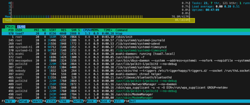
And finally, running a script that forces swap space usage:

Just one small warning, using swap on a usb drive is very slow. You may also want to reduce swappiness in order to help improve performance:
toad7@toad7:~ $ cat /proc/sys/vm/swappiness
60
toad7@toad7:~ $ sudo sysctl vm.swappiness=10
vm.swappiness = 10


 0.
0.